OPERATION MANUAL
TABLE-TOP FILLER/CAPPER
7282 SPA ROAD | NORTH CHARLESTON, SC 29418
PHONE: 843-569-2530 | FAX: 843-576-0798
WWW.INLINEPACK.COM

CAUTION!
Persons operating this machinery are reminded to observe their own company safety policies.
In addition, the following safety rules should be observed:
DO NOT REACH INTO THE MACHINE WHILE IT IS IN OPERATION.
USE ONLY THE CORRECT TOOL FOR THE JOB BEING DONE.
STAY ALERT, REMEMBER LOCATION OF CONTROL SWITCHES.
PROPER VENTILATION IS REQUIRED WHERE FILLING MACHINES ARE IN USE.
MAINTENANCE
The main electric switch supplying power to the machinery should be locked out or
disconnected when repairs are performed on this equipment.
Machine should be cleaned and inspected regularly. All safety switches must be operable,
attachments secure and machine free of broken glass and paper.
Do not hand lubricate when the machine is in operation.
Work area should be kept clean and as dry as is practical.
The repair or adjustment of this equipment should be performed only by persons qualified
through technical training and ability, as assigned by your company.
OPERATION
All guards should be securely in place before operating the machine.
Company rules on eye protection should be followed.
Loose clothing or jewelry such as neckties, rolled sleeves, over blouses, bracelets, watches and
rings should not be worn when operating the machine.
Report all malfunctions, unusual operation and defects immediately.
Please exercise caution with any moving parts, including the conveyor and any pinch or drive
rolls.
Stop the machine before placing hand or arms near or into any area where moving parts are
located.
TABLE OF CONTENTS
OPERATIONAL AND MAINTENANCE SAFETY RECOMMENDATIONS
SECTION ONE – GENERAL INFORMATION
1.1 Terminology of Machine
1.2 Specifications and Requirements
1.3 Functional Description of Machine
1.4 Basic Machine Controls and Screen Settings
SECTION TWO – UNCRATING AND INSTALLATION
2.1 Power and Air Connections
2.2 Installing in Production Line
2.3 Leveling Base of Machine
2.4 Adjusting Components of Machine
SECTION THREE – PREPARING FOR OPERATION
3.1 Set Conveyor Rails
3.2 Adjust Machine Settings
3.3 Adjust Sensors
SECTION FOUR – OPERATIONAL ADJUSTMENTS
SECTION FIVE – PERIODIC MAINTENANCE, CLEANING, AND LUBRICATION
5.1 Maintenance
5.2 Cleaning the Machine
5.3 Lubrications
SECTION SIX – TROUBLESHOOTING
6.1 Nothing Works at All
6.2 Operational Inconsistencies
SECTION SEVEN – OPTIONS AND/OR SPECIAL COMPONENTS SUPPLIED WITH MACHINE
SECTION EIGHT – PARTS LIST AND DIAGRAMS
SECTION ONE – GENERAL INFORMATION
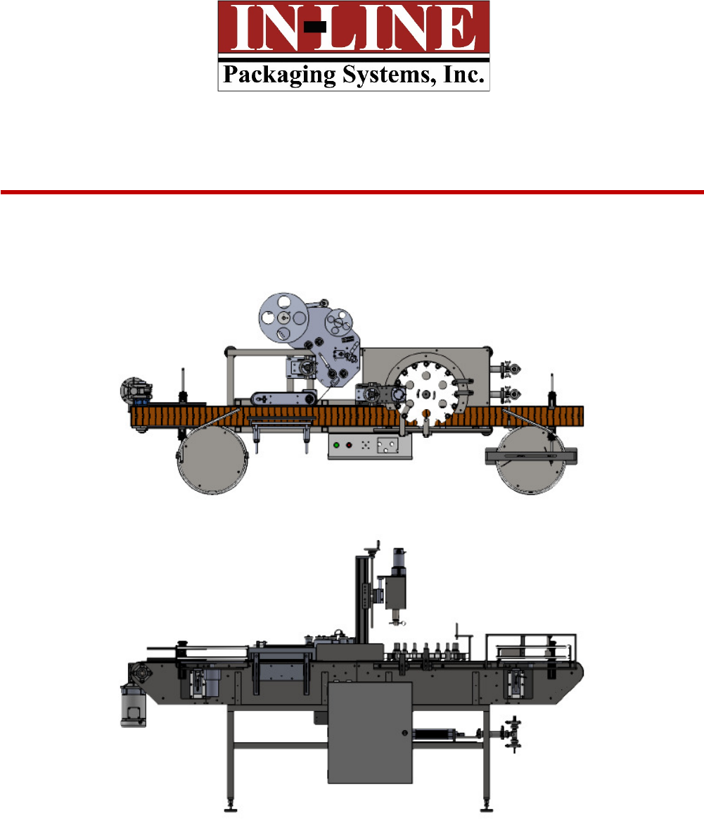
1.1 TERMINOLOGY OF MACHINE
Table Top Filler/Capper
1. Feed Table 4. Indexing Star Wheel
2. Cap Tightener 5. Piston/inlet
3. Label Head
1
2
3
4
5
1.2 SPECIFICATIONS – STANDARD MACHINE
ITEM
SPECIFICATION
CONVEYOR WIDTH
4.5
INCHES STANDARD
MACHINE SPEED
VARIABLE UP TO
30
BPM
L
ABEL HEIGHT
4.5 INCHES
OVERALL DIMENSIONS
48x
108
INCHES STANDARD
ELECTRIC REQUIREMENTS
1
2
0VAC 6
AMPS
AIR REQUIREMENTS
90
PSI
@ 4
-
6
CFM
Features:
• 304-stainless steel frame construction
• Aluminum and plastic parts throughout the mechanism
• Stainless steel filling nozzles
• Positive container indexing and centering
• Hand crank adjustment for different height containers
1
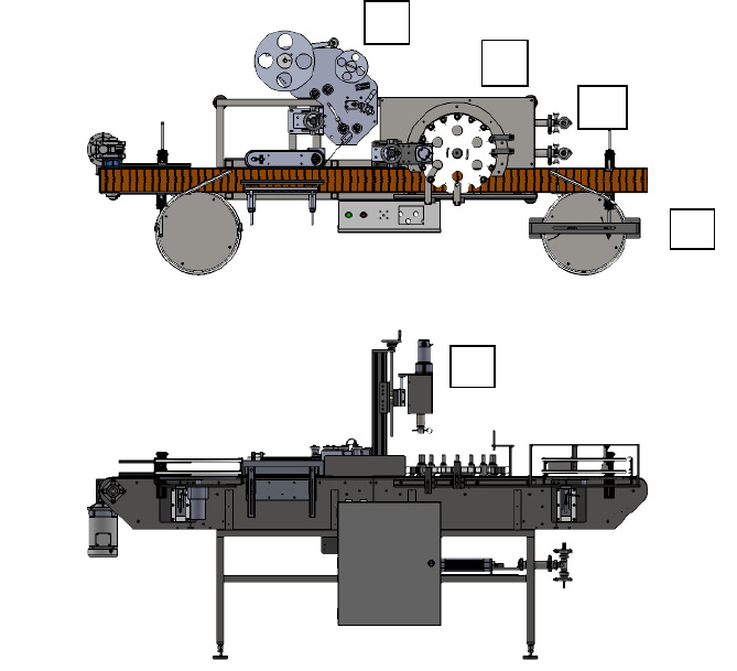
1. Feed Table Sweep Arm
2. Filling piston Unit.
3.
3 W
ay
Rotary valve
2
3
1
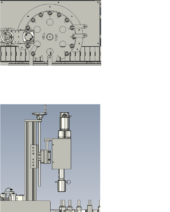
1. Fill Volume Adjustment
Collar
2. Cap Torqueing Head
3.
Indexing Star Wheel
2
3
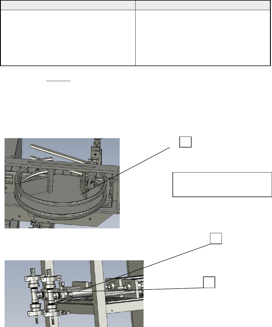
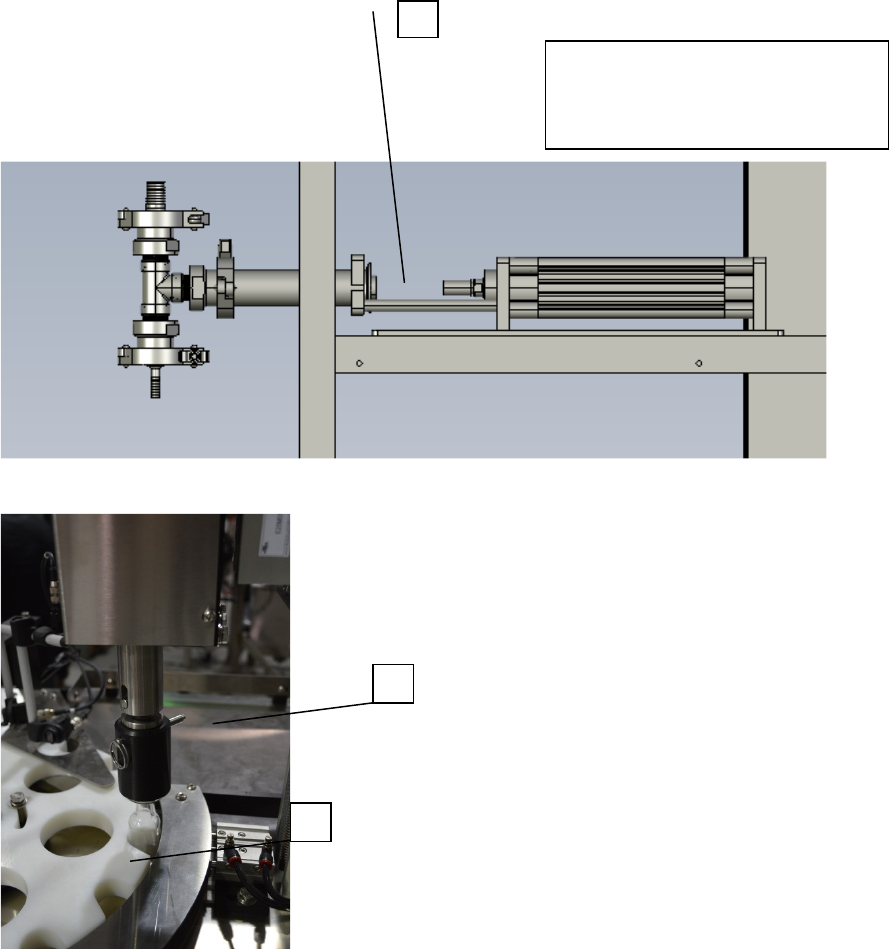
1
2
1. Fill Nozzle (2 on dual piston
models)
2. Fill Position Bottle Sensor
Reflector or sensor only on
some model
1
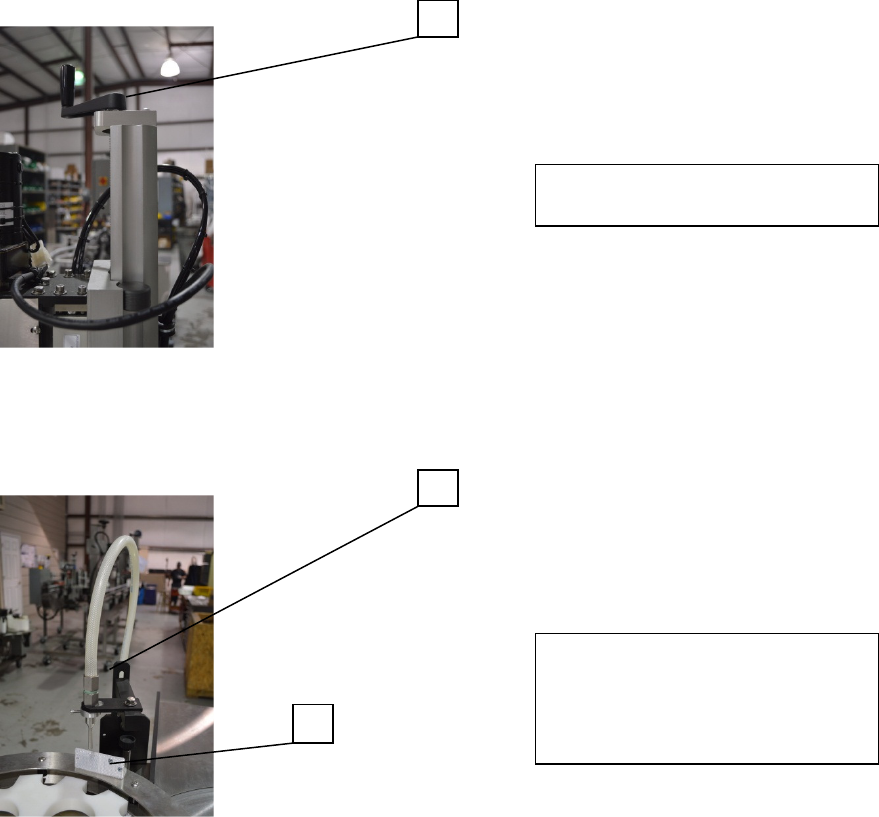
1. Cap Torqueing height
Adjustment
1.3 FUNCTIONAL DESCRIPTION OF MACHINE
The Inline Table-Top Filler is an automatic filling machine that can fill various sizes of
containers with medium to low viscosity.
The filler indexes bottles into position using an inductive prox sensor by detecting the
star pockets’ indexing recessed screws, and stopping the star under the filling head and
cap tightener positions . The piston pump(s) start and the fill nozzle(s) dispense for
filling. Once the filling cycle is complete the star wheel indexes to the next position (set
by the filling cycle time). A new set of bottles is indexed into position and the cycle
continues so long as bottles are present on the infeed conveyor. The star wheel only
indexes when a bottle supply is detected at the infeed lane on the star wheel.
The pistons when signaled to dispense will change the 3-way valve from charge to
dispense position allowing product to flow our of the nozzle. When the fill is complete
and the piston reverses the 3-way valve also reverses allowing product from the supply
tank to be pulled into the piston for the next cycle.
If Cap delivery is purchased the caps are sorted in a vibratory bowl and fed through a
horizontal chute, bottles detected in the cap delivery location trigger a cap to be
pressed onto the top of a filled bottle.
Caps then index to the cap tightener where caps are torqued. The torque setting is
adjusted by removing the cover and adjusting the magnetic clutch using its 0-5 scale.
Bottles then exit the capping location returning to the conveyor and travel to the
labeling head if equipped.
The bottle rotation speed is detected by an encoder on the wrap station, after a the
bottle is detected by the product sensor traveling on the conveyor and a delay (label
delay) is met the label feeds, this should be set to occur just as the bottle enters the nip
of the wrap belt and backpad. The labels while feeding are thread3ed through a fork
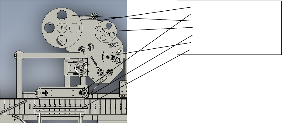
1. Label Applicator Head
2. Wrap Station
3. Feed Reel
4. Takeup Reel
5. Peel Tip
6. Label pinch Rolls
7.
Wrap Backpad
sensor which detects the gap between labels. When a label gap is detected the label
feeds the distance (Gap/Flag Delay) required to fully dispense off the end of the peel tip.
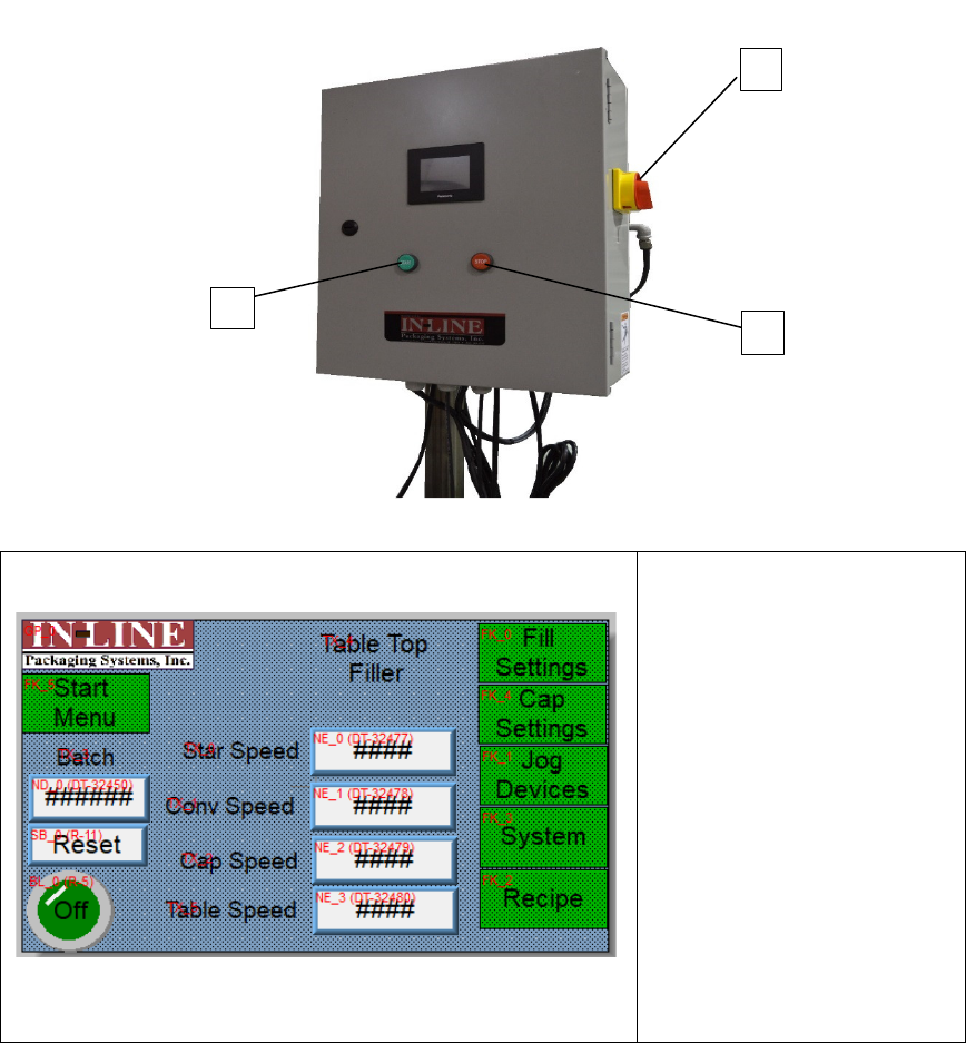
1.4 BASIC MACHINE CONTROLS (exact box location may vary depending on application)
1. Main Power Switch
2. Start Push Button
3. Stop Push Button
SCREEN SETTINGS
Main Screen
Starwheel Speed: Enter speed of
star as a percentage, other
speeds are a scale of 0-1200.
Batch Count: displays current
batch count
Batch Reset: Press to reset count
to 0
Fill Settings: access screen for
Filling
Cap Settings: access screen for
cap control
Jog Device : Manually Jog devices
Recipe Functions: save/recall
previous settings
System Settings: change
settings/devices
1
3
2
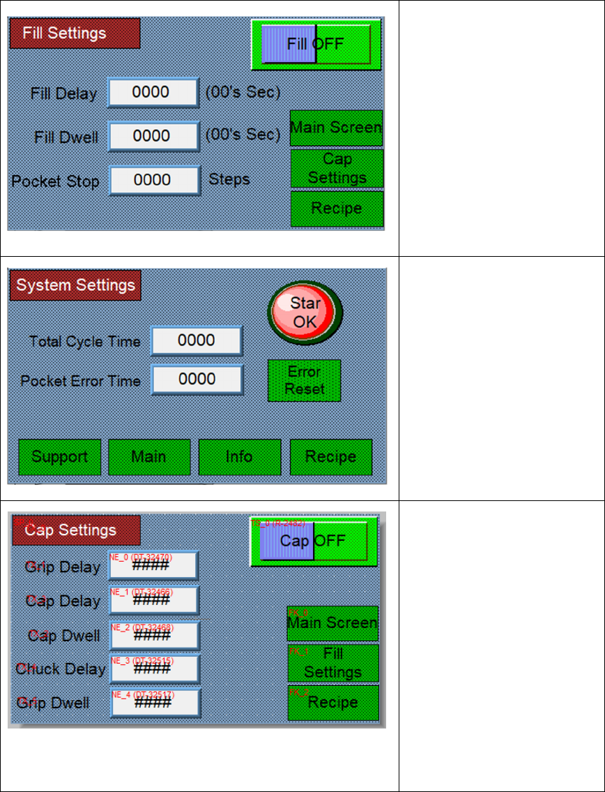
Filler Settings Screen
Fill On/Off: Push to Toggle On or
Off
Fill Delay: Push Number to enter
new delay. This is time for the
piston to dispense after the star
index is complete.
Fill dwell : Push Number to enter
the total length of the fill cycle.
This must be long enough to
allow the piston to fully stroke.
Pocket Stop: This is the number
of the star travel distance after
the index sensor triggers.
System Settings Screen:
Cycle Time: This is the total
length of the machine cycle, all
filling and capping functions must
be set within the length of this
cycle.
Pocket Error: If the star wheel
moves this many steps without
seeing a star pocket the machine
will stop and error( check that
the pocket eye and reflector are
working if this occurs)
Cap Settings:
Grip Delay: This number is the
time delay for the gripper to
extend to capture the bottle for
capping.
Capper Delay: This number is
time after the gripper closes
before the cap head lowers.
Capper Dwell: This is the length
of time the capping head stays
down for torqueing.
Chuck Delay and Grip Dwell:
These times are used with a
pneumatic chuck to delay the
closing of the jaws and delays the
opening of the gripper.
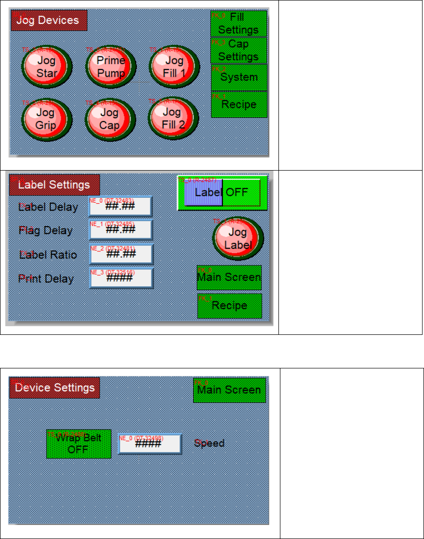
Device Jog Settings Screen:
Starwheel, the pump and devices
can be manually jogged from this
screen.
Jog Fill and Prime Pump can
be used for clearing air from
the filling lines prior to
starting.
Label Settings Screen:
The label delay is the distance for
starting a label after bottle
detection.
The Flag delay is the label stop
distance after a gap.
Label Ratio is the label feed
speed relative to the wrap
speed.
Print delay is the print delay if
the inkjet coding option is
purchased.
Device Settings Screen:
Wrap Belt on/off selection.
The speed is a scale of 0-1200
inches per minute.

System Settings Screen:
The timeouts stop the machine if
either occurs.
No labels present on the
machine, or if a gap is not
detected when the label is
feeding. 100=1 Second
SECTION TWO – UNCRATING AND INSTALLATION
2.1 POWER AND AIR CONNECTIONS
A grounded electrical male plug is provided with the machine, and is connected to the main
electrical enclosure on the rear side of the machine. Plug this into any grounded receptacle. For
compressed air, behind the electrical enclosure is an air filter/reservoir with a 1/4” male quick
disconnect attached. You can supply compressed air to the machine by either a mating quick
disconnect on the end of an air hose, or you can permanently pipe air to the machine using
standard pipe and connecting directly into the air filter using threaded pipe connections. If you
permanently pipe into the system we recommend a cut-off valve be mounted at the machine.
Some changeover adjustments are easier if the operator is able to temporarily turn off the air
pressure.
2.2 INSTALLING IN PRODUCTION LINE
Move the machine into its permanent location. Adjust the conveyor height of the machine to
match the heights of the adjoining machines as required. Leveling pads are provided with the
Econo-Filler that allow you some vertical adjustment. If necessary, make spacing blocks to raise
the height. Additional lineal space is provided on each end of the machine to allow a crossover
from or to the next machine. Position the conveyor ends as close to each other as possible and
then use conveyor rails to guide the containers across narrow dead plates onto the conveyor.
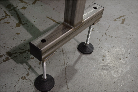
2.3 LEVELING THE BASE MACHINE
Once the machine is installed, level the main conveyor through the machine by using a bubble
level. Place the bubble level along the length of the machine. Leveling the machine is important
to the flow of the line as it allows for more seamless transitions between machines. The
squaring and straightness of the base machine will ensure the machine operates correctly.
SECTION THREE – PREPARING TO FILL
3.1 LOADING PRODUCT INTO THE TANK
Fill the supply tank 2/3 full of product (Customer Provided). Visually monitor tank level
throughout bottling run and refill when desired
3.2 SET TABLE
The feed table speed is adjusted using the table speed in the screen. The sweep arm can be
adjusted for optimal feed. Note the table should not be completely filled
3.3 ADJUST HEIGHT AND SPACING OF NOZZLES
The height of the nozzle is adjusted using SAE wrenches, the centering over the bottle is also
adjustable. The fill level is adjusted by limiting the stroke of the piston drive air cylinder using
the plastic knob near the indexing star. Use supplies angle wrench for loosening the jam nut.
3.4 ADJUST capping height.
The capping head is vertically adjustable using the hand crank, the speed of the spindle rotation
is adjusted using the speed setting on screen.
3.5 Adjust label settings.
The label height is adjusted using the handwheel on the vertical stand. The angle adjustment is
managed using the turnbuckle and smiley face plate under the label head. The wrap and back
pad should be set to ensure continuous rotation during labeling, be careful to avoid over
tightening this adjustment.
Label tracking on the peel tip and takeup is managed using the jam screw on the pinch roll stop
vertical block. Tighten the top screw to track upward, the bottom to track downward.
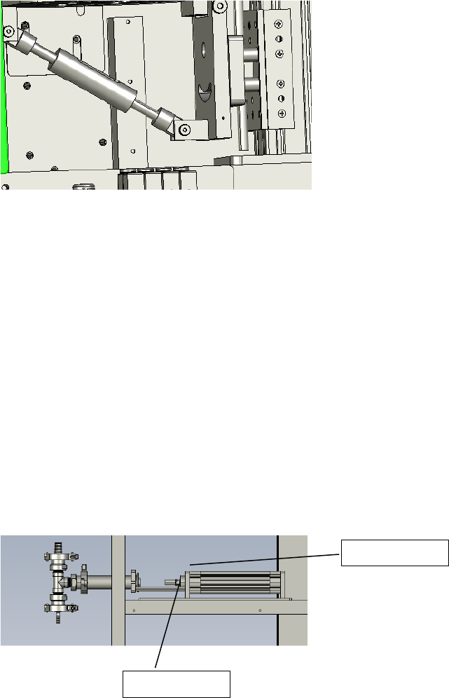
SECTION FOUR – OPERATIONAL ADJUSTMENTS
4.1 ADJUSTING FILL LEVELS
As stated above the fill volume is adjusted using the shaft collars on the Air cylinder push rods.
To adjust the level log the piston on in the settings screen this will extend the piston to its fill
complete position. Allowing a greater travel increases volume. For instance moving the shaft
collar to the left will increase the fill level, moving it to the right will decrease travel of the piston
and reduce fill volume.
On two head units each piston will half fill a bottle to increase overall throughput and reduce
the fill cycle time.
The fill speed is set using the flow controls on the air cylinders closing the flow control on the
left will lower the dispense speed. Closing the flow controls on the right will lower the piston
charging speed.
Flow Controls
Shaft Collars
SECTION FIVE – PERIODIC MAINTENANCE, CLEANING, AND LUBRICATION
MAINTENANCE
Ensure that you perform a monthly visual inspection for wear on the fill heads, conveyor chain,
and pump leaks.
CLEANING THE MACHINE
The Table-Top Filler comes in stainless and aluminum construction. Cleaning the machine
regularly is recommended using soap and water, but not by spraying the machine down.
LUBRICATION
The only lubrication points on the machine are:
1. Any threaded rod for linear motion should have light oil applied to it periodically to prevent
rust and to keep the mechanism moving freely. The conveyor bearings should be lubricated
with a grease gun once every 3-6 months.
SECTION SIX - TROUBLESHOOTING
The list below represents a few scenarios in which troubleshooting may need to occur.
6.1 NOTHING WORKS AT ALL/POWER IS ON BUT NOTHING WORKS
a) Check main power. Is machine plugged in? Is main power switch turned on?
b) Check fuses inside control panel.
c) Are speed controls turned up above zero?
6.2 OPERATIONAL INCONSISTENCIES (NOTHING IS BEING FILLED)
a) Confirm that filling is on and that the bottle eye is changing states between bottles.
b) Confirm that air supply is on.
